The button is wired between IO4 and GND, with nothing connected to 3.3 V. How does the ESP32 read a press, and what pin setting makes that work?
Enable the internal pull-up on IO4. Released, the resistor pulls the pin up to 3.3 V and it reads 1. Pressed, the button connects the pin to GND and it reads 0. The button is active low.
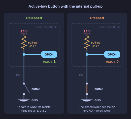
* The pull-up gives the pin a level when the switch is open; the switch only ever pulls it down. *
A switch can only connect or disconnect. Wired to GND, it can pull the pin down when closed, but it does nothing when open. Something else has to supply the high level for the open state. That is the pull-up: a resistor of tens of kilohms (about 45 kΩ on the ESP32) between the pin and 3.3 V, built into the chip and switched on in software.
- Released: no current path to GND. Almost no current flows into an input, so there is almost no voltage across the resistor and the pin sits at 3.3 V. It reads 1.
- Pressed: the switch connects the pin straight to GND, so it reads 0. A small current flows through the resistor (3.3 V / 45 kΩ ≈ 73 µA). Because the resistor is large, that current is negligible. With a plain wire instead of a resistor, pressing would short 3.3 V to GND.
So the logic is inverted: pressed = 0. That is called active low, and the code has to account for it (pressed = (gpio_get_level(4) == 0)).
Wiring to GND with a pull-up is the usual choice because ground is always nearby on a board and the ESP32 provides the pull-up for free. The opposite (button to 3.3 V, pull-down enabled) works too and gives active-high logic. GPIO34-39 have no internal pulls at all, so a button on one of those needs an external resistor.
Go deeper:
 SparkFun — Pull-up resistors — the button circuit, the current through the resistor, and how to size it.
- Wikipedia — Pull-up resistor — pull-up vs pull-down and where else they appear (I2C, open-collector outputs).