Question
In a setup where an ESP32 reads a BME280 sensor and a laptop shows temperature, humidity and pressure live, what does each part do?
Answer
The BME280 measures, the ESP32 reads it over I2C and sends the readings on, and a client on the laptop receives and displays them in real time.
The chain has three stages, and each one does a single job:
- Sensor (BME280). Measures temperature, relative humidity and barometric pressure, and keeps the latest readings in its registers. It does not decide when anyone reads them.
- IoT device (ESP32). Is the bus master. It asks the sensor for fresh values over I2C, converts the raw register values into units with the sensor's calibration data, and forwards the readings off the board.
- Laptop. Runs the receiving client (in the demo an Arduino-based one) that shows the three values as they arrive.
The split is the usual IoT shape in miniature: a cheap, dumb sensor; a small device that does the measuring and the talking; and a bigger machine that collects and presents the data. Scaling it up means a gateway or a cloud service instead of the laptop. The device in the middle stays the same.
Go deeper:
 Random Nerd Tutorials — ESP32 with BME280 — the same demo end to end, with wiring and the Arduino code that reads the sensor.
- Bosch Sensortec — BME280 — the manufacturer's page with the datasheet and measurement ranges.
Note saved — thanks!
Question
How is a BME280 breakout wired to an ESP32 over I2C, and why are the sensor's pins labelled SCK and SDI rather than SCL and SDA?
Answer
Four wires: VIN to 3V3, GND to GND, SCK to IO22 (SCL, the clock) and SDI to IO21 (SDA, the data). The chip also speaks SPI, and SCK/SDI are its SPI pin names, which double as the I2C clock and data pins.
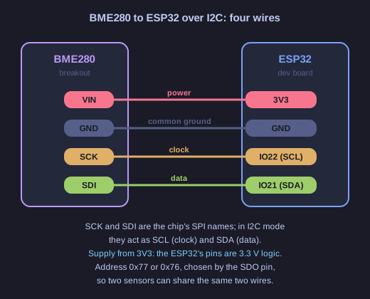
* Two of the four wires carry power, two carry the bus. *
| BME280 | ESP32 | Role |
|---|---|---|
| VIN | 3V3 | Power |
| GND | GND | Common reference for every signal |
| SCK | IO22 (SCL) | I2C clock, driven by the ESP32 |
| SDI | IO21 (SDA) | I2C data, both directions |
Three details make this wiring work:
- The pin names. The BME280 supports both SPI and I2C. Its pins are named for SPI (SCK = serial clock, SDI = serial data in), and in I2C mode the same pins serve as SCL and SDA. The SDO and CS pins stay unconnected for I2C.
- 3.3 V, not 5 V. The ESP32's I/O runs at 3.3 V and its pins are not 5 V tolerant. Many breakouts (Adafruit's among them) have a regulator and level shifters, so they would accept 5 V. Cheap modules often do not, and the bare chip is a 3.3 V part. Powering from 3V3 is right for both.
- IO21 and IO22. These are the default I2C pins of the Arduino core on a generic ESP32. The ESP32 can route I2C to almost any free GPIO, so they are a convention you can change in code, not a hardware requirement.
Go deeper:
- Adafruit — BME280 breakout pinouts — which pin does what in SPI and in I2C mode, and the address jumper.
- Arduino-ESP32 — I2C API — the default SDA/SCL pins and
setPins()to move them. - Wikipedia — I²C — the two-wire bus, open-drain lines and addressing.

Note saved — thanks!