Quiz Entry - updated: 2026.10.20
How is a BME280 breakout wired to an ESP32 over I2C, and why are the sensor's pins labelled SCK and SDI rather than SCL and SDA?
Four wires: VIN to 3V3, GND to GND, SCK to IO22 (SCL, the clock) and SDI to IO21 (SDA, the data). The chip also speaks SPI, and SCK/SDI are its SPI pin names, which double as the I2C clock and data pins.
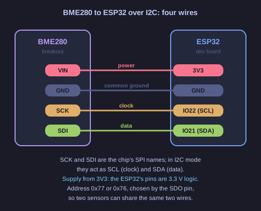
* Two of the four wires carry power, two carry the bus. *
| BME280 | ESP32 | Role |
|---|---|---|
| VIN | 3V3 | Power |
| GND | GND | Common reference for every signal |
| SCK | IO22 (SCL) | I2C clock, driven by the ESP32 |
| SDI | IO21 (SDA) | I2C data, both directions |
Three details make this wiring work:
- The pin names. The BME280 supports both SPI and I2C. Its pins are named for SPI (SCK = serial clock, SDI = serial data in), and in I2C mode the same pins serve as SCL and SDA. The SDO and CS pins stay unconnected for I2C.
- 3.3 V, not 5 V. The ESP32's I/O runs at 3.3 V and its pins are not 5 V tolerant. Many breakouts (Adafruit's among them) have a regulator and level shifters, so they would accept 5 V. Cheap modules often do not, and the bare chip is a 3.3 V part. Powering from 3V3 is right for both.
- IO21 and IO22. These are the default I2C pins of the Arduino core on a generic ESP32. The ESP32 can route I2C to almost any free GPIO, so they are a convention you can change in code, not a hardware requirement.
Go deeper:
 Adafruit — BME280 breakout pinouts — which pin does what in SPI and in I2C mode, and the address jumper.
- Arduino-ESP32 — I2C API — the default SDA/SCL pins and
setPins()to move them. - Wikipedia — I²C — the two-wire bus, open-drain lines and addressing.