How do the three common sensor buses UART, I2C and SPI differ?
UART links exactly two devices over TX/RX with an agreed baud rate; I2C shares two wires among many addressed devices; SPI uses four wires and a chip-select per device for the highest speed.
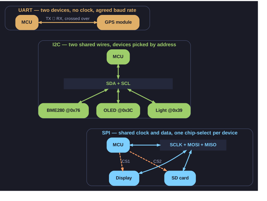
* Three buses, three wiring patterns: point-to-point, shared and addressed, or shared with a select line per device. *
Every board in the IoT spectrum lists "GPIO, UART, SPI, I2C" in its specs. They are the three ways a processor talks to sensors, displays and other chips:
| UART | I2C | SPI | |
|---|---|---|---|
| Wires | TX, RX (crossed over) + GND | SDA (data), SCL (clock) | SCLK, MOSI, MISO + one CS per device |
| Devices | Two, point-to-point | Many on one bus, picked by a 7-bit address | Many, picked by pulling their CS line low |
| Clock | None; both sides agree on a baud rate (e.g. 115200) | Shared clock from the controller | Shared clock from the controller |
| Speed | Up to ~1 Mbit/s typically | 100 kHz / 400 kHz, faster modes exist | Tens of MHz |
| Typical use | Debug console, GPS, flashing firmware | Temperature/pressure sensors, small OLEDs | Displays, SD cards, fast ADCs |
The trade-off is wires against speed. I2C needs only two pins no matter how many sensors hang off it, which is precious on a small board; SPI costs an extra pin per device but is much faster and full-duplex. UART has no clock at all, which is why both ends must be set to the same baud rate or you see garbage characters.
Tip: "I2C = I too see" (two wires, addresses); SPI = more wires, more speed.
Go deeper:
 SparkFun — I2C — addressing, pull-up resistors and the start/stop conditions on the two wires.
- SparkFun — Serial Peripheral Interface (SPI) — chip select, clock modes, and why SPI is full-duplex.